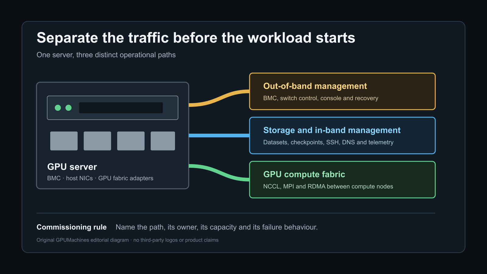
A new GPU server can have every cable connected and still have the wrong network design. If the BMC, SSH access, dataset reads and distributed GPU traffic all depend on one unplanned path, a busy checkpoint write can delay administration, a switch failure can remove the recovery route, and a configuration error can expose privileged interfaces to the wrong users.
The commissioning goal is not to create the maximum number of networks. It is to give each traffic class the isolation, capacity and recovery behaviour that its role requires. For one workstation, that may mean a dedicated BMC port plus two carefully controlled VLANs. For a multi-node training cluster, it usually means a separate out-of-band management network, an in-band management path, a storage path and a dedicated GPU compute fabric.
This guide explains how to make that decision before production workloads start. It covers the port map, routing and access questions, the difference between physical and logical separation, and the tests that show whether the finished design behaves as intended. For fabric sizing and leaf-spine port arithmetic, use the separate non-blocking GPU cluster network guide.
Name the traffic planes before assigning ports
Do not start with VLAN numbers or switch models. Start with the systems that must communicate, the services they need and the failure cases they must survive.
| Traffic plane | Typical traffic | Normal trust boundary | Main design concern | | --- | --- | --- | --- | | Out-of-band management | BMC, switch management, console servers, power distribution units | Privileged infrastructure operators and approved automation | Recovery access must survive host and production-network faults | | In-band management | SSH, provisioning, DNS, time, scheduler control, monitoring and package access | Administrators, control-plane services and monitored nodes | Predictable access without exposing management services to workload or public networks | | Storage | Dataset reads, checkpoint writes, model artefacts, NFS, parallel file systems and NVMe over Fabrics | Compute nodes and authorised storage systems | Sustained throughput, burst handling, redundancy and correct MTU or RDMA configuration | | GPU compute | NCCL, MPI, GPUDirect RDMA and other east-west job traffic | Participating compute nodes and fabric-control services | Low latency, high bandwidth, congestion control and topology consistency | | External or service traffic | User sessions, APIs, data ingest, registry access and corporate services | Defined client and service networks | Keep north-south access from becoming an accidental path into the compute fabric |
NVIDIA's current DGX BasePOD reference architecture uses three principal networks: an InfiniBand compute network, an Ethernet fabric for system management and storage, and a separate out-of-band management network. That is a useful reference, not a mandatory template. The right answer depends on the server interfaces, workload, storage protocol, staff skills and acceptable failure domains.
The important decision is explicit ownership. Every interface, subnet, VLAN, VRF and default route should belong to a named traffic plane. An unlabelled spare port is not a resilience plan.
Keep out-of-band management independent
The BMC can power-cycle the host, open a remote console and mount virtual media. It remains reachable when the operating system has failed, which is why its path deserves stronger separation than an ordinary application VLAN.
Use the dedicated BMC interface where the server provides one. Connect it to a restricted management switch or management fabric that also carries switch, console and facility-management endpoints. Permit access from named jump hosts, administrator VPN ranges and required monitoring or automation systems. Do not provide a general route from user, workload or public networks.
Physical separation gives the clearest failure boundary, but it is not complete by itself. A management switch with an unrestricted uplink can still expose every controller. Apply routing policy, access control, authentication and logging at the boundary. The IPMI and BMC commissioning guide covers those controls in detail.
Some platforms can share a production NIC between the host and BMC. Treat that as a specific design exception. Record the firmware mode, switch configuration, VLAN handling and behaviour when the host is powered off. A shared port may be acceptable in a space-constrained single-server deployment, but it weakens the clean recovery boundary and makes cabling evidence less obvious.
Ask one practical question during acceptance: can an authorised engineer reach the BMC when the host is down and the production data path is unavailable? If the answer depends on the same failed switch, firewall or identity service, the path is not as independent as the operating plan assumes.
Separate in-band management from BMC access
In-band management runs through the host operating system. It includes SSH, DNS, time synchronisation, provisioning, scheduler control, telemetry and configuration management. This traffic needs more bandwidth and broader service access than the BMC, but it should not be reachable from every application or tenant network.
A dedicated pair of host management ports is the clearest option. On smaller systems, in-band management may share redundant Ethernet adapters with ordinary service traffic or storage. If it does, separate the traffic with VLANs or VRFs, restrict routing between them and retain enough capacity for administration during a storage burst.
Do not put a default route on every interface. Multiple competing defaults create asymmetric paths, confusing source-address selection and firewall results. Choose which plane owns ordinary outbound access, then add explicit routes for the others. Inspect the effective result from the host rather than relying on a diagram:
``text ip -br link ip -br address ip route show table all ip rule show ``
Record which interface receives DNS and time configuration. A multi-homed host can resolve names correctly while sending the query through the wrong network. The preceding SSH, users, DNS and time guide explains how to test the identity and access path before driver and cluster work proceeds.
Decide whether storage needs its own physical fabric
Storage behaviour varies more than its label suggests. A software repository and an occasional file copy do not have the same network demand as parallel training reads or multi-node checkpoint writes.
Use a physically separate storage fabric when the workload can consume a large share of the available link bandwidth, when storage and compute have different operational owners, when a storage fault must not disturb management, or when the protocol requires a controlled RDMA configuration. Dedicated interfaces also make utilisation and fault evidence easier to interpret.
Logical separation can be reasonable for a single server or a modest cluster when traffic volume is bounded and the shared switches, uplinks and adapters have enough capacity. VLANs and VRFs separate forwarding and policy; they do not create bandwidth. A 100 GbE port carrying two VLANs remains one 100 GbE port, with one queueing system and one physical failure domain.
If storage and in-band management share links, test administration during sustained reads and checkpoint writes. If storage and GPU compute share a RoCE fabric, test them together with the intended congestion-control configuration. A clean microbenchmark on an otherwise idle network does not prove the converged design.
NVIDIA's Ethernet Storage Fabrics guide describes redundant active-active designs using MLAG and explains that storage deployments may use active-active or active-backup NIC bonding. Do not assume that a bond doubles throughput for every flow. Link aggregation normally distributes flows according to a hash; one transfer may remain on one member. The failover mode, storage-client behaviour and switch configuration must agree.
Give GPU traffic a deliberate path
Distributed GPU jobs exchange traffic between nodes through Ethernet or InfiniBand. This is the scale-out compute fabric. NVLink and NVSwitch inside a server are separate scale-up paths and do not replace the external network.
For a multi-node training cluster, use dedicated compute-fabric adapters and switches unless a supported converged architecture has been designed and tested for the actual workload mix. Map each adapter to its PCIe and NUMA location, identify the nearest GPUs or NVSwitch domain, and keep the rail or plane labelling consistent across every node.
NVIDIA's BasePOD documentation shows this separation at the hardware level. DGX B200, H200 and H100 systems use dedicated high-speed adapters for the compute fabric, separate adapter paths for management and storage, and an out-of-band port for BMC access. Custom servers differ, so obtain the manufacturer's block diagram rather than inferring locality from the rear panel.
On Ethernet, RoCE is not enabled safely by assigning a VLAN and selecting a large MTU. Endpoints and every switch in the traffic path need a compatible configuration. NVIDIA's current Cumulus Linux storage-fabric guide states that its RoCE setup covers buffer pools, traffic classification, priority mappings, Priority Flow Control, Explicit Congestion Notification, queues and scheduling. Other switches use different commands and supported profiles.
Apply the validated recipe for the exact NIC, switch and software release. Do not copy PFC thresholds from another platform or enable global pause across unrelated traffic. PFC can protect a selected priority from loss, but a poor configuration can spread congestion and make failures harder to isolate.
For InfiniBand, preserve the same discipline. Confirm subnet-manager ownership, partitions where used, routing, port state, firmware and cable mapping. A link reporting active does not prove that traffic follows the intended rail or that every node has symmetric paths.
Physical separation, VLANs and VRFs solve different problems
The word separate can describe several controls. They are not interchangeable.
| Method | What it separates | What it does not guarantee | | --- | --- | --- | | Dedicated NIC and switch fabric | Physical bandwidth, cabling and switch failure domain | Correct access policy, host routing or independent power | | Dedicated NIC on a shared switch | Host interface and port capacity | Switch, uplink and control-plane independence | | VLAN | Layer 2 broadcast domain and policy attachment point | Reserved bandwidth, separate buffers or a separate switch failure domain | | VRF | Routing table and layer 3 reachability | Physical capacity or protection from a shared control-plane failure | | QoS class | Queue treatment during contention | Security boundary or extra link capacity | | Host firewall | Service reachability on that host | Fabric-wide segmentation or protection before the host firewall starts |
A good small design may combine them: a physical BMC network, a bonded Ethernet pair with separate management and storage VLANs, and a dedicated InfiniBand compute fabric. A larger cluster may give each plane its own adapters, leaf switches, routing domain and monitoring.
Avoid adding hardware merely to make a diagram look more enterprise. Extra NICs and switches add firmware, optics, cables, rack space, power and spares. Buy physical separation where the traffic volume, trust boundary or failure policy needs it. Use logical separation where shared capacity is acceptable and can be proved under load.
Three practical starting designs
One GPU workstation or standalone server
Use the dedicated BMC port on a restricted management network. The host can use one redundant Ethernet bond for administration, storage and client access if the workload is modest. Put management and storage in separate VLANs, restrict inter-VLAN routing and define one normal default route. There is no scale-out GPU plane until a second compute node is introduced.
This is the lower-cost option. Its limitation is shared capacity and a shared switch failure domain. Test remote access while the storage path is busy, and document what happens if one bond member or switch is lost.
Two to eight training nodes
Use a dedicated BMC network. Give hosts a redundant Ethernet path for in-band management and, where capacity permits, storage. Use a separate high-speed Ethernet or InfiniBand fabric for NCCL and other east-west compute traffic. This closely follows the traffic separation in NVIDIA's BasePOD reference architecture without requiring every implementation detail of a DGX deployment.
If storage traffic approaches the available Ethernet capacity or has strict latency and recovery requirements, move it to dedicated adapters and switch ports. Do not wait for unexplained training stalls before identifying that checkpoint traffic and SSH share the same queues.
Larger cluster or mixed-tenant environment
Treat out-of-band management, in-band management, storage, GPU compute and external services as distinct planes. Give each a written capacity, access and failure policy. Use dedicated fabrics where contention or trust boundaries justify them, and use VRFs or equivalent routing separation between control domains.
At this scale, consistency matters as much as topology. Automate switch and host configuration, reserve addressing, label every rail, collect per-plane telemetry and compare nodes for drift. One interface with an unexpected default route can bypass the intended controls.
Build the host and switch record
Before configuration, create a port-level table for every server:
| Record | Example evidence | | --- | --- | | Physical port and MAC address | chassis label, ip -br link and adapter inventory | | PCIe address and NUMA locality | server block diagram and operating-system topology output | | Traffic plane | OOB, in-band management, storage, GPU compute or external | | Switch and port | leaf name, port ID, cable or optic identifier | | Link mode | Ethernet or InfiniBand, speed, width, FEC and MTU | | Logical attachment | VLAN, VRF, subnet, bond or rail | | Routes and gateways | intended routing table and source network | | Allowed peers and services | access-control rule owner and purpose | | Redundancy role | active-active, active-backup or independent rail | | Failure expectation | connectivity and permitted performance reduction after one fault |
Keep the BMC record separate from the host record even when both are printed on the same chassis label. The BMC has its own address, firmware and access policy.
On the switches, capture the matching port description, VLAN or routing assignment, negotiated state, error counters and transceiver identity. A cable schedule should let an engineer trace a host interface to a switch port without following a cable by hand.
Test the separation before accepting the system
Test from the source networks that real operators and services will use. Running every check locally on the GPU node can hide a broken access-control boundary.
1. Prove intended reachability
From an approved jump host, reach the BMC and host management address. From a normal user or workload network, confirm that BMC and switch-management services are not reachable. Test the permitted DNS, time, monitoring and package paths rather than granting broad egress because one service failed.
2. Inspect host routing
Confirm the source address and interface selected for every important destination. Look for multiple defaults, routes learned on the wrong interface and unintended forwarding between planes. If the host is not a router, verify that IP forwarding is disabled or explicitly controlled.
3. Check link and fabric identity
Record negotiated speed, link state, MTU, errors and transceiver data. For RDMA fabrics, confirm that the expected RDMA devices and ports are present. For GPU compute adapters, compare the node topology with the approved rail map.
4. Exercise each plane independently
Test management access, a representative storage read and write, and point-to-point compute-fabric traffic. Use the production protocol and realistic transfer sizes. Record the test endpoints, software versions and result; do not substitute a generic line-rate target for an application requirement.
5. Run mixed traffic
Continue an SSH session and telemetry collection while storage traffic is active. If storage and compute share any path, run the expected dataset or checkpoint pattern alongside a representative collective test. Watch latency, throughput, packet drops, ECN marks, PFC pause counters and job step time as applicable.
6. Remove one supported path
Disable or disconnect one bond member, switch uplink or other approved redundant path during a maintenance test. Confirm which sessions survive, how routes converge and what steady-state capacity remains. Do not perform an unplanned failure test on a production system.
7. Prove recovery access
With the host operating system stopped or its production interface unavailable, reach the BMC through the documented route. Verify that the console works and that the event log records the correct time. This closes the loop between network design and operational recovery.
Common commissioning failures
The BMC is on a dedicated port but still reachable from the office network. The cable is separate; the routing policy is not. Restrict the management boundary and retest from both approved and denied sources.
Storage is on another VLAN but an SSH session stalls during checkpoints. The VLANs share a link, queues and uplinks. Measure contention, then reserve capacity, adjust the supported QoS design or add physical bandwidth.
A bonded pair shows two active links but one transfer uses only one. The link-aggregation hash keeps that flow on one member. Test several flows and the real storage client before assuming aggregate bond capacity applies to one job.
RoCE works between two nodes and becomes unstable across the fabric. Endpoint and switch configuration may not be consistent end to end. Compare firmware, priority mapping, ECN, PFC, MTU and routing against the supported design for the installed releases.
GPU traffic uses the wrong interface. Multiple reachable subnets, route metrics or application settings may select a general-purpose NIC. Bind the test to the intended interface, inspect the route and confirm the framework's network selection.
The recovery network fails with the production network. Shared switching, routing, authentication or power created a hidden common dependency. Decide whether the requirement is ordinary remote management or genuine out-of-band recovery, then fund the appropriate independence.
The handover record
A finished network handover should include:
- the traffic-plane diagram and port map;
- host and BMC addresses, without passwords or private keys;
- switch ports, VLANs, VRFs, subnets and routing ownership;
- permitted source networks and required services;
- NIC, DPU or HCA firmware and driver versions;
- bond, MLAG, rail and failover design;
- MTU and RoCE or InfiniBand configuration references where applicable;
- healthy-state and failure-state capacity assumptions;
- reachability, mixed-traffic and failover test results;
- telemetry locations and the owner for future changes.
Redact credentials, tokens, private keys and unnecessary public addresses from the handover copy. Store secrets in the organisation's approved secrets system and reference the retrieval process instead.
The network is ready when an engineer can explain which path each traffic class uses, why it is allowed, what it shares, and what happens when one component fails. A rack photograph and a set of green link lights do not answer those questions.
Plan the interfaces with the server order
Network separation is cheaper to design before the server and switches are purchased. Adapter slots, PCIe locality, optics, cable reach and switch ports can constrain the final result. Use the GPU cluster configurator to define the compute nodes, then review the management, storage and compute fabrics as one bill of materials.
For a standalone or small-cluster deployment, ask GPUMachines to identify the lowest-complexity design that still meets the access, workload and failure requirements. For multi-node training, request a port-level fabric and acceptance plan rather than a switch-speed headline.