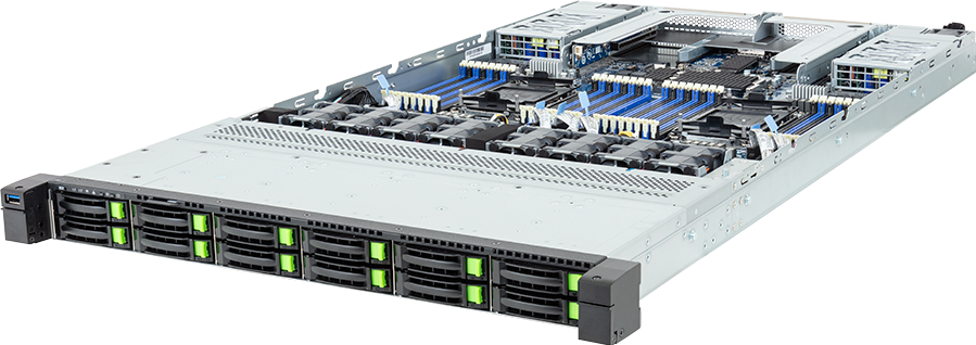
The GIGABYTE R184-S92-AAV1 packs two Intel Xeon 6 sockets, 32 DDR5 slots and 12 hot-swap 2.5-inch drives into 1U. The most important word in that storage specification is not Gen5. It is shared.
There are 12 physical front bays. Each can support NVMe, SATA or SAS in the appropriate configuration, but the server does not have 12 bays for each interface. A valid quote therefore starts with one combined 12-drive plan, the controller required for SATA or SAS, and the network needed to move data beyond the chassis.
Configure the GIGABYTE R184-S92-AAV1 after defining the drive mix, service workload and fabric speed. This review covers the air-cooled AAV1 model and ordering family 6NR184S92DR000AAV1*; it does not transfer claims from the liquid-cooled LAV1 variant.
What GIGABYTE specifies
The R184-S92-AAV1 is a 1U dual-processor server based on the MS94-FS0 motherboard. GIGABYTE positions it for networking and hybrid or private cloud use, but the physical design also suits databases, virtualisation, software-defined storage and data services near GPU clusters.
| Area | Published specification | Design consequence | | --- | --- | --- | | Chassis | 1U, 438 x 43.5 x 815 mm | Dense rack use, high-speed fans and an 815 mm depth check | | CPUs | Two LGA 4710 sockets, Xeon 6500P/6700P/6700E | Two NUMA domains and up to 350 W per socket | | Memory | 32 DDR5 slots, eight channels per CPU | Symmetric population matters for bandwidth and capacity | | Front storage | 12 shared 2.5-inch Gen5 NVMe/SATA/SAS-4 bays | One combined 12-drive limit | | Internal storage | Two Gen5 x4 M.2 plus one Gen5 x2 M.2 | Separate boot or service devices, with different CPU attachment | | Expansion | Two FHHL Gen5 x16 slots | HBA, RAID, accelerator or PCIe NIC placement | | OCP | Two OCP NIC 3.0 Gen5 x16 slots | One high-speed network path from each CPU domain | | Base network | Two Intel i350 1GbE plus management LAN | Provisioning and management, not a 12-drive data plane | | Power | Two 1600 W Titanium PSUs | Full output requires 200 to 240 V input | | Cooling | Eight 40 x 40 x 56 mm fans | Data-centre acoustic and airflow expectations |
GIGABYTE's product page, 2026 Intel server guide and hardware manual agree on the core topology. Regional pages differ slightly on the two-DIMM-per-channel RDIMM figure, showing 5200 or 6000 MT/s in current copies. That is a reason to confirm the ordered BIOS and DIMM QVL, not to choose the faster number for marketing copy.
One 12-bay pool, not 36 drives
Tri-mode backplanes are easy to represent badly in a configurator. If the database stores 12 NVMe, 12 SATA and 12 SAS as separate rows and simply adds them, the customer sees 36 front positions. The physical server has 12.
The correct model lets all three interfaces draw from one shared maximum. A customer can select six NVMe and then use the remaining six positions for qualified SATA or SAS devices, subject to the storage card and cabling. Selecting 12 NVMe should leave no front positions for another interface.
All 12 bays have PCIe 5.0 NVMe connectivity. The lane map is balanced: six front NVMe paths connect to CPU 0 and six to CPU 1. That topology can reduce unnecessary cross-socket traffic when storage processes, memory and network queues are placed with care. It does not guarantee application performance on its own. Filesystem, queue depth, drive endurance, controller mode, NUMA policy and the external network still set the useful result.
SATA and SAS need an additional storage card. The buyer must decide whether the workload needs hardware RAID, an HBA that exposes individual drives, or a controller mode supported by the chosen software-defined storage platform. A RAID card selected only from headline throughput can create the wrong failure domain or hide the drive telemetry an application expects.
Mixing interfaces also needs a reason. NVMe can carry latency-sensitive databases, active datasets or model cache. SAS may suit dual-port enterprise designs and established controller stacks. SATA can provide lower-cost capacity. A random mixture complicates spares, rebuild behaviour and monitoring. Document the role of each media tier before placing the order.
Three M.2 positions are not one uniform group
The internal M.2 count is three, but the links and ownership differ. Two 2280/22110 positions connect to CPU 1 at PCIe 5.0 x4. The M.2 slot on the I/O board accepts a 2280 device and connects to CPU 0 at PCIe 5.0 x2.
That is useful for separating boot or hypervisor media from the front hot-swap pool. It does not automatically provide a validated three-drive boot mirror. Firmware support, device qualification, service access and recovery procedure have to be checked. If boot redundancy is required, state it directly in the quote and acceptance plan.
An internal device can also be harder to replace than a hot-swap front drive. A service that writes heavily to its boot or log volume may belong on the front pool or on a supported mirrored module rather than on a difficult-to-reach M.2 card.
Dual Xeon 6 and the NUMA map
The two Socket E2, LGA 4710 positions support Intel Xeon 6500P, 6700P and 6700E processors. GIGABYTE permits CPUs up to 350 W. The P and E families serve different host profiles: P-core models can favour strong per-core behaviour, while E-core models offer higher core density for parallel services and virtual machines.
The right CPU depends on what the storage node actually does. A simple backup target may not justify two high-end processors. Compression, erasure coding, encryption, deduplication, virtualisation, database execution and many high-speed network queues can use substantial host compute. Per-core software licensing can make an oversized CPU especially expensive.
For the full I/O topology, install both sockets. GIGABYTE states that some PCIe and memory functions may be unavailable when only one CPU is fitted. Six front NVMe paths and one OCP slot belong to each CPU, while the conventional PCIe slots also divide one per socket. A single-CPU configuration can therefore remove more than compute capacity.
NUMA awareness matters when the server is busy. A process reading drives attached to CPU 0, using memory attached to CPU 1 and transmitting through the CPU 1 OCP NIC creates traffic across the socket link. Modern operating systems can manage much of this, but placement should be observed under the real workload rather than left to assumption.
Thirty-two DIMMs and the MRDIMM boundary
Each processor has eight memory channels and 16 slots, giving 32 positions in total. GIGABYTE publishes RDIMM support up to 6400 MT/s at one DIMM per channel. Two DIMMs per channel operate at a lower speed. The exact current rate should be checked against the regional specification, CPU and BIOS because published copies show 5200 and 6000 MT/s.
MRDIMM is listed up to 8000 MT/s and only with selected Xeon 6 P-core processors in a one-DIMM-per-channel layout. That condition is easy to lose when a generic parts catalogue maps every LGA 4710 memory item into every product. An 8800 MT/s MRDIMM from the same socket generation is not qualified by the R184-S92-AAV1 specification.
For virtualisation and storage services, memory capacity can be more valuable than the last step of speed. Page cache, metadata, database buffers, virtual machines and network services all compete for RAM. Populate both CPUs symmetrically, respect channel rules and confirm that the chosen processor supports the memory technology.
Two PCIe slots and two OCP slots
The R184-S92-AAV1 has two full-height, half-length PCIe 5.0 x16 slots, one from each CPU. It also has two OCP NIC 3.0 Gen5 x16 slots, again split across the processors. Both OCP positions support NCSI.
This is a useful arrangement for a storage system. OCP can carry the main data interfaces while the conventional slots remain available for an HBA, RAID card, compression accelerator or another qualified device. The 1U height and half-length limit still apply. A full-length GPU is not the intended use, and an add-in card must suit the available cooling and bracket.
If SATA or SAS consumes one PCIe slot, there is only one conventional slot left. That makes the dual OCP layout more important. Decide the controller and network architecture together rather than filling the storage bays first and asking where the NIC will fit later.
The onboard network is a management starting point
Two rear 1GbE ports use an Intel i350-AM2 controller. A separate 10/100/1000 management port connects to the AST2600 BMC. This is a sensible base for provisioning, low-rate host services and out-of-band administration, but it cannot carry the useful output of 12 fast NVMe drives.
A production storage role may need 25, 100, 200 or 400GbE. An AI cluster can use Ethernet or InfiniBand depending on its compute fabric and storage design. Pick the adapter only after defining clients, aggregate throughput, replication, backup windows and failure behaviour. Then verify the switch ports, optics, cables, driver, firmware and CPU attachment.
Two ports are not automatically redundant. They need separate switch paths and a tested failover design. The BMC should remain on a restricted management network rather than sharing the data plane.
Power, airflow and installation
Dual 1600 W 80 PLUS Titanium power supplies provide redundancy, subject to the final system load. GIGABYTE lists a maximum of 1000 W per module at 100 to 127 V and the full 1600 W at 200 to 240 V or supported 240 V DC input. A high-power dual-CPU, fully populated configuration should therefore be planned around high-voltage rack feeds.
The PSU rating is capacity, not expected consumption. The rack planner should add the configurable processors, DIMMs, drives, controllers and NICs to a base allowance for the board, BMC, backplane, risers and eight high-speed fans. GIGABYTE does not publish a measured component-only value, so the 300 W barebone entry is an engineering estimate that should be replaced after acceptance measurements.
Eight 40 mm fans create the airflow needed in 1U and the noise expected of a data-centre system. The 815 mm chassis also needs rear connector and cable clearance. Confirm cabinet depth, rails, PDU position and whether the optional three-section rail and cable-management arm are required.
Where the R184-S92-AAV1 fits
This server is a good candidate for virtualisation, private-cloud service nodes, database hosts, software-defined storage, backup staging and local data services beside GPU infrastructure. It gives buyers 12 tri-mode hot-swap positions without consuming 2U, and it keeps two Gen5 OCP slots available for a serious network.
It is not a general answer to every storage problem. Large-capacity 3.5-inch media belongs in another chassis. A workload needing many HBAs, accelerators or GPUs will find 1U restrictive. A data service that cannot use the bandwidth of 12 NVMe devices may spend more on drives and power than it gains in application performance.
Compare the R184-S92-AAV1 with a 2U alternative using the complete design: drive media, controller, CPU licences, memory, NICs, switch ports, rack power and service method. Density is valuable only when it does not turn maintenance or cooling into the limiting cost.
Acceptance checklist
1. Confirm the exact R184-S92-AAV1 air-cooled suffix and ordered part number. 2. Treat the front as one 12-bay shared NVMe/SATA/SAS pool. 3. Record the count and role of every drive interface. 4. Select and qualify an HBA or RAID card for SATA or SAS. 5. Map six front NVMe paths, one PCIe slot and one OCP slot to each CPU. 6. Install both processors when the full I/O topology is required. 7. Populate memory symmetrically and keep MRDIMM at the published 8000 MT/s ceiling. 8. State the role and redundancy policy for all three internal M.2 devices. 9. Size the data fabric from workload traffic, not the onboard 1GbE ports. 10. Verify PSU output, PDU diversity and failure margin at the available voltage. 11. Check 815 mm chassis depth, rear cable space and rail choice. 12. Test CPU, memory, drives and network together while recording rack power and thermals.
FAQ
Does the R184-S92-AAV1 support 12 NVMe, 12 SATA and 12 SAS drives at once?
No. It has 12 physical front bays shared by those interfaces. The combined front-drive count cannot exceed 12.
Can all 12 front bays use Gen5 NVMe?
Yes. GIGABYTE lists six Gen5 NVMe connections from each CPU. SATA and SAS use the same physical bays and require a suitable storage card.
How many internal M.2 slots are available?
There are three. Two are Gen5 x4 2280/22110 positions from CPU 1. The I/O board provides one Gen5 x2 2280 slot from CPU 0.
Does it support 8800 MT/s MRDIMM?
The current product specification lists MRDIMM up to 8000 MT/s with selected P-core Xeon 6 processors at one DIMM per channel. An 8800 MT/s module needs a later exact-model qualification before it should be offered.
What happens if only one CPU is installed?
GIGABYTE warns that some PCIe and memory functions may be unavailable. The full storage, memory and expansion topology is designed around two processors.
Is the onboard 1GbE enough for an NVMe storage node?
Not for serious data traffic. The server provides two Gen5 x16 OCP slots and two Gen5 x16 PCIe slots for faster network adapters and controllers.
Does the server need 200 to 240 V power?
Full 1600 W PSU output requires 200 to 240 V AC. At 100 to 127 V, GIGABYTE lists a maximum of 1000 W per module.
Is this a GPU server?
No. It is a CPU and storage platform with half-length expansion slots. Buyers needing full-length accelerator cards should choose a server designed and qualified for them.
Verdict
The R184-S92-AAV1 is a credible high-density 1U server for buyers who need dual Xeon 6 compute, a balanced 12-drive Gen5 NVMe topology and two fast OCP network positions. Its best designs use both CPU domains deliberately and reserve the conventional slots for the storage controller or another service card.
Its main catalogue risk is arithmetic. Twelve tri-mode bays do not become 36 physical drives, and three M.2 devices do not belong in the same shared pool. The memory limit is also exact: 8000 MT/s MRDIMM, not every faster part sold for LGA 4710.
Open the GIGABYTE R184-S92-AAV1 configurator with the drive mix, controller mode, host-memory target, network speed and rack voltage ready for compatibility review.
Technical sources
- GIGABYTE R184-S92-AAV1 product page
- GIGABYTE R184-S92 hardware manual
- GIGABYTE 2026 Intel server guide
- Intel Xeon 6 product information
GIGABYTE can revise component support and specifications. Confirm the exact suffix, current QVL, controller, drive list and BIOS before purchase.